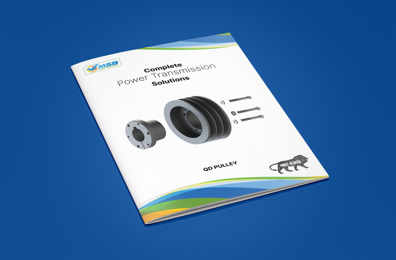
 QD Pulley
MSB Power Transmission manufactures QD Pulleys and Quick Detachable bushings in Mumbai, India. The QD bushings are designed for easy installation and removal, featuring a split flange and tapered design for a secure clamp on the shaft similar to a shrink fit. Removal is facilitated using the pull-up bolts as jack screws. Sizes offered include QH, JA, SH, SDS, SD, SK, SF, E, and F, initially available in pilot bore and customizable by re-boring to meet specific shaft requirements. Bushings from ‘JA’ to ‘F’ are drilled for Reverse Mounting. MSB provides QD pulley bushings in both inch and metric sizes, ensuring 100% interchangeability with licensed manufacturers’ OE products.
| BVTIJOH
*% |
BPSF SBOHF GPS: | A | B | % | & | F | ( | 4FU TDSFX TJ[F | AWFSBHF XFJHIU | % TJHOBUJPO | |||
| NJO | NBY | ||||||||||||
| 4UE LFZ XBZ | 4IBMMPX LFZ XBZ | LH | MCT | ||||||||||
| +A C/h | 1 | 1−A/d | 0,31 | 1,38 | 2,00 | 1,00 | 0,56 | 0,12 | 10−24 | 0,4 | 0,9 | 1)F +A-© | |
| 4) A/b | 1−C/h | 1−AA/af | 0,43 | 1,88 | 2,63 | 1,31 | 0,81 | 0,12 | A/d | 0,5 | 1 | 1)F 4)-© | |
| 4%4 A/b | 1−AA/af | 2 | 0,43 | 2,18 | 3,18 | 1,31 | 0,75 | 0,12 | A/d | 0,5 | 1 | 1)F 4%4-© | |
| 4% A/b | 1−AA/af | 1−AE/af | 0,43 | 2,18 | 3,18 | 1,81 | 1,25 | 0,12 | A/d | 0,7 | 1,5 | 1)F 4%-© | |
| 4K A/b | 2−A/h | 2−A/b | 0,56 | 2,81 | 3,88 | 1,93 | 1,25 | 0,22 | E/af | 0,9 | 2 | 1)F 4K-© | |
| 4F A/b | 2−E/af | 2−AC/af | 0,63 | 3,13 | 4,63 | 2,06 | 1,25 | 0,22 | E/af | 1,4 | 3 | 1)F 4F-© | |
| & G/h | 2−G/h | 3−A/b | 0,88 | 3,83 | 6,00 | 2,75 | 1,63 | 0,25 | C/h | 4,5 | 10 | 1)F &-© | |
| F 1 | 3−E/af | 3−AE/af | 1,00 | 4,43 | 6,63 | 3,75 | 2,50 | 0,34 | A/b | 5,2 | 11,5 | 1)F F-© | |
| + 1−G/af | 3−C/d | 4−A/b | 1,13 | 5,14 | 7,25 | 4,63 | 3,18 | 0,38 | E/h | 8,2 | 18 | 1)F +-© | |
| M 2−AE/af | 4−C/d | 5−A/b | 1,25 | 6,50 | 9,00 | 6,75 | 5,18 | 0,41 | C/d | 16,8 | 37 | 1)F M-© | |
| / 2−G/af | 5−A/h | 6 | 1,50 | 7,00 | 10,00 | 8,12 | 6,25 | 0,56 | C/d | 25,9 | 57 | 1)F /-© | |
| 1 2−AE/af | 5−AE/af | 7 | 1,75 | 8,25 | 11,75 | 9,38 | 7,25 | 0,63 | G/h | 54,4 | 120 | 1)F 1-© | |
| 8 4 | 7−A/b | 8−A/b | 2,00 | 10,42 | 15,00 | 11,38 | 9,00 | 0,50 | 1 | 113,4 | 250 | 1)F 8-© | |
| 4 6 | 8−A/d | 10 | 2,75 | 12,13 | 17,75 | 15,25 | 12 | 0,75 | 1−A/d | 181,4 | 400 | 1)F 4-© | |
Mounting Process:
Ensure the tapered cone surfaces of the bushing and the interior of the driven product are clean and free of any anti-seize lubricants.
Slide the QD bushing onto the shaft, aligning it properly, and install the key.
Position the QD bushing on the shaft and tighten the set screw firmly using a standard Allen wrench, avoiding excessive force.
Tighten the pull-up bolts alternately and evenly until they reach the specified tightness indicated in the torque table.
Dismounting:
Remove the pull-up bolts and insert them into the tapped holes in the sheave or sprocket against the QD bushing to release the cone grip.
Loosen the set screw and slide the QD bushing off the shaft.
